Category: Projects

  • Brighter lights

    Version 1.1 of the Luxeon LED test board was waiting for me when I returned from the frozen northlands. I spent some time soldering in the through-hole components this morning and then did the LEDs this evening. The LEDs were a little tricky but they all work and I didn’t burn myself which counts as success. I have some pictures of the finished product. The lights are bright. Very bright. The LM317 regulators get really hot. I have some heat sinks I’m going to have to attach but I was erroneously running the thing at +25V which may be part of the problem. The regulator dissipates power equal to (V_in – V_out) * I_load so if V_in is 25V, V_out is only 11V (3.4V forward voltage * 3 LEDs rounded up for other loss) and I_load is 320mA the power dissipated is 4.5W which is an awful lot. I’ll try again soon with the voltage set more sanely. Anyway, pictures.


    Lights on

    I think the next step is to get the Arduino in and useful so I have a little bit of time to wait.

  • Lights

    I had some parts come in today. Six white LEDs to play with and some 2cm square prototyping boards. After the practice and note taking from last week setting up the simple current control circuit went quickly and I got the LEDs lit up. The new custom PCB should be in the mail and the Arduino duemilanove is back in stock at Sparkfun which means mine should be shipping soon if it hasn’t already. Exciting times.

    lights_th
    LEDs in the breadboard


    Heatsink mockup

    The design work has progressed fairly well. I think I’ve figured out how to get all 20 of the lights to be independently controllable and the whole circuit should be fairly efficient. I may need to redo the design spec for the individual current controls though since the switching frequency is currently 10kHz but the new PWM controllers are higher frequency (~500Hz normally) which means I should bump the current switching frequency up to 40kHz or so. I’ll read through the datasheet again before going to the trouble to be sure.

    Next steps are making up a real heat sink (probably with the remains of an aluminum can) with my little prototype boards attached and wiring up the play LEDs and populating the PCB when it arrives. It remains to be seen if I can solder the temperature-sensitive surface mount LEDs without ruining them but I have a few ideas. Everything else is through hole and basically doesn’t care about heat unless you just stab the glowing tip of the iron through the part.

    On an unrelated note I get to visit Minneapolis for work. The forecast has been getting rosier every time I look at it. They’re predicting a balmy 20°F (up from 14°F) and 20% chance of snow for Thursday and 22°F on Friday which is practically shorts weather provided you are a bear or a wolf or some kind of other fur-covered non-human creature. It’s retarded cold for us people and I’m remembering The Cremation of Sam McGee by Robert Service.

  • Shop

    I am whupped. This weekend was spent mostly in the garage. There are new shelves on the walls replacing the craptacular free standing metal and MDF shelving I had before. It’s wire shelving that has standards which hang from a top rail like the Elfa stuff they sell at the container store though it has a different brand name. I wonder if it’s actually the same stuff. I still need two more shelves since the Home Depot was running low when I was there but I already have most of the stuff off the floor which was the goal. The table saw is now on its new rolling platform parked neatly under the hanging shelves which is very nice. It took me an hour and a half to put the “mobile base” together though, mostly due to the fact that math is hard.

    The jointer came from Amazon on Thursday and I put that together this afternoon. I think it may actually be heavier than the table saw. It works well though so I’m looking forward to the start of the cabinet building. Of course I didn’t actually manage to do any actual woodworking this weekend with all of the shelving, organizing, cleaning and construction. Maybe next weekend. Also, I have six cans of WD-40. I think I’m set on that for the rest of my life.

    jointer

  • Twinkle

    I wanted to get an idea of how much room I had to work with inside the stars. Using the pattern from mathworld I made a small stellated dodecahedron with the “unit pentagrammic edge length” roughly 0.7″ which was what would fit on a sheet of paper. According to maths this makes the star diameter ~3.5″. This is what it looks like with the top open.

    paper star 1

    I need to be able to mount each LED on a small circuit board (0.6″ square) and then mount that onto a heat sink. The design for the heat sink is pretty simple though the name for the particular solid is a mouthful. It is a Small Rhombicuboctahedron. Well, it’s not exactly one of those but it’s close enough. I cut one of those out of an index card and taped it together too. Here it is next to the star.

    paper star 2

    The 3.5″ star has a dodecahedron open in the center which has an indiameter of 1.5″. The simulation heat sink is a little more than 1″ diameter. This star is smaller than the minimum size I’m actually thinking about for the lights. The smaller light will probably be 5″ diameter (2.25″ center opening) and the larger 6.5″ (3″ center opening). Ultimately this means that the LED block will fit comfortably inside. Yay maths.

    paper star 3
    It fits!

    paper star 4
    om nom nom

  • LED test board v1.1

    This is the revised LED test board I sent to BatchPCB. It has a few minor improvements beyond the fixed slug connections. According to SparkFun’s PCB design guide traces that will carry up to 500mA should have 16 mil traces so I made sure all of mine were 16 mil. I also added labels for the regulators, capacitor, resistors and the switch. Since I have all of the components here now I also printed out a 1x view of the top of the board and made sure all the parts have the right footprints and what not. If the first board is any indication I should get v1.1 around the end of the month.
    v1.1 schematic
    v1.1 PCB
    v1.1 layout test

  • I suck and that's sad

    I messed up my PCB design. The prototype board I haven’t even received yet will not work. It has two parallel groups of three 1 watt Luxeon I emitters in series and the heat sink slugs for each LED are electrically connected to two big copper planes on the PCB. If I had read the application brief describing assembly in addition to the datasheet and design guide I would have known that you aren’t supposed to do this. Why you ask? The reason is explained in the reliability datasheet which isn’t even listed on the product page where the datasheet, thermal design guide and other application briefs are on their website. I had to use google to discover it.

    LED_internalInside the LED package are two parallel circuits. The first is the LED connected between the anode and cathode: anode -> LED -> cathode. The second goes like this: anode -> zener diode preventing current from anode -> heat sink slug -> zener diode preventing current from cathode -> cathode. The reverse breakdown voltage of the diodes is 7V so if you have three LEDs in series with +10V on top after the current regulator and GND on bottom the voltage at that first zener diode at the top of the chain is actually 10V and it will break down and nothing will work.
    led circuit
    At this point I have two options. Option the first: there exists thermally conductive, electrically non-conductive epoxy. You can even buy small batches of it for purposes like attaching heat sinks to ram chips and so on. Arctic Silver makes some that is apparently good and which can be had for $13 or so from Fry’s. Applying this to the bond pad for the LED would theoretically electrically isolate the slug from the board but still conduct heat to it. This is a bit ugly and may not work depending on your interpretation of the Arctic Silver website and documentation. Option the second is to order the updated board in which I have fixed the problem. This is appealing because I have also fixed a few other minor, not-show-stopping things and have included some extra labeling on the silk screen. It would mean another two weeks or so wait and double the cost of the thermal adhesive.

    If nothing else this has been very educational. Thanks to Brian Neltner whose website (ahem) illuminated my design error during his discussion of LED choice. His art collaboration project is very cool. I will probably go with the new board.

  • Lots of stuff

    I had a little vacation last week. It was great. Didn’t bring the camera though so you’ll just have to use your imagination. Since MoMA is having their van Gogh exhibit now and it’s unlikely that I’ll be able to see all of those paintings again in my lifetime I figured out a way to go and see it. I flew to Philadelphia Thursday, had a nice dinner at Brasserie Perrier that night which was superb. I had pumpkin ravioli to start followed by the crispy duck breast and a side of root vegetable au gratin and pear crisp for dessert. It was all very good and the service was excellent. I got up early Friday morning, took the Amtrak into Penn Station in Manhattan and walked the twenty blocks up to the museum. First of all, the membership is great. There was a huge line to get in and a timed entry ticket system for the van Gogh both of which I got to skip completely thanks to my magic plastic card. The van Gogh exhibit itself was very crowded but completely worth the trip. The Starry Night Over the Rhône is amazing. I haven’t seen a picture of it that does it justice. In fact I ended up going through the show three separate times throughout the day.

    The rest of the museum is fantastic as well. There is a gallery of the painting and sculpture highlights on their website that is representative of the collection. I was in awe all day long. It’s funny to go into a place and see things which were in your textbooks growing up. I’m just going to start linking in things I saw that were superb. Boccioni, Rousseau, Picasso, also Picasso, Pollock, Monet. I briefly considered hosting the images locally and in-lining them here but I think that might have some unpleasant copyright implications so instead you should just click the links and enjoy the show.

    I also saw the Liberty Bell and Independence Hall in Philadelphia and had a Philly cheese steak and a slice of genuine New York style pizza. It was a great trip. Hopefully I’ll get to go back again soon.

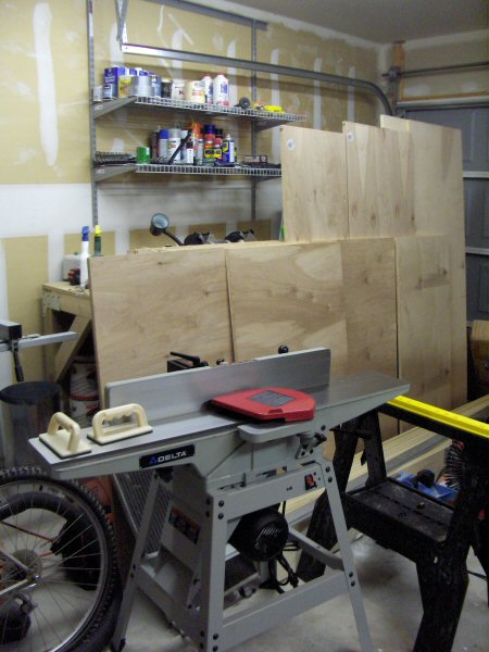
    Let’s see, other stuff. Before I went on vacation I finished the cutting diagrams and bought the wood for my bookshelves. I’ll start breaking that down into the component parts this weekend. This project has been a long time in the works and I’m not expecting it to get done quickly but I’d like to have the individual cases constructed by the end of the year at least. I’m pretty happy with how the design came out. The asymmetry is minimal considering the limitations of the room. My current complaints are that a) Engineered bamboo plywood costs about ten times what it should meaning I will have to get creative for the desktop and b) Lowes doesn’t sell my choice of jointer anymore so I ended up ordering one from Amazon. They’re giving me free shipping though so that’s nice.

    The not-so-super, not-so-secret dining room lighting project also continues. The electronic proof of concept has been designed and laid out and the PCB is in queue to be manufactured on the other side of the world. The company providing this service is BatchPCB which takes a bunch of board designs puts them all onto one big 11″ x 15″ panel and then has them cut apart. It’s a pretty good deal for prototyping. When it comes time to have 120 half-inch square boards made I may need to re-evaluate my vendor. The whole design process has turned out to be much less difficult than I had expected it to be. SparkFun has good tutorials on using Eagle to do schematic and PCB design and the software only took about a week to get comfortable with. I’m sure it’s quite a bit more powerful than I’m currently exploiting but it was quick to pick up. All the actual electronic parts and my shiny new soldering iron came in last week so now I just need the board to finish up and I’m ready to see if I’m any good at routing electrons.

    With all of the projects in progress and the fab shutdown and the holidays and art shows coming up it’s looking to be a busy winter. Plus there’s this video game I used to play that has an expansion next week. I may have to get some folks to lash me to the mast lest I be overcome by its call. I have to admit that though my account remains inactive my client is up to date as of this week so all it would take now is a moment of weakness and a scroll of resurrection.

  • Small Stellated Dodecahedron

    moravian star lightA while back I received a very nice pendant light for my entry way from my mother. The catalog at Lighting Universe calls it a moravian star though I’m not sure that’s technically correct based on looking at the google results for that term. It is however a fairly specific mathematical solid called a Small Stellated Dodecahedron. A regular dodecahedron has 12 sides each of which is a regular pentagon. If you imagine each of the sides as being part of a plane and then extend that plane outwards and look to see where they all intersect one of the sets of intersections makes this small stellated dodecahedron. It’s a nice looking solid and it has some fun mathematical properties, not the least of which is that the angle between any two adjacent faces is the same. This becomes important later.

    triangle blanksI decided that I wanted to try to make one of these. There’s an ultimate motive behind this but that particular project is so far down the priority list that it might as well be in my will. One star made out of wood is an achievable, short term kind of project. I bought a few pieces of pre-dimensioned pine and some 1/2″ MDF for making jigs and got to work. The first step was to cut 60 triangles out of the pine. I ended up cutting more like 80 due to a few errors early on and so I would have a few extras to practice on. That was fairly easy. Put a gap block on the table slotted into one of the guide grooves to get a constant gap, set the miter gauge on the slide to 18° to get the right angle on the triangles (36°, 72°, 72° isosceles) and then flip the board after each pass.

    beveled trianglesThe next part is a little more difficult. Once you have your triangles you need to bevel the edges so they will fit together correctly to make the points of the star. If you use the math from the mathworld page you get an angle between planes of 116.57°. That means the bevel angle needs to be half that or 58.3°. The table saw is not really set up for sub degree precision on cuts but you can get there with, again, some trial and error. It is also helpful to have a few jigs to stick the piece in because that means you keep your soft, meaty fingers away from the hungry saw and, depending on how you build the jig, you can cut more than one bevel at a time. Once I got the jigs made, tested and refined it ended up taking about four hours to cut the three bevels per piece. Once they’re all cut they look like this.

    After all of the pieces are ready I started gluing them. The way I found easiest was to glue two triangles together and let that dry instead of trying to put all five per point together at once. When you have two sets of two and one single it’s easier to make the pyramidal point. After I’d made all 12 pyramids I glued three at a time into a quarter of the structure. Then finally glued the four quarters into the final star. The gallery of pictures is here and I’ve put a few more thumbnails below. I think it turned out ok and I gave it to a friend who liked it. Now I need to finally get my ass in gear on my book shelves. Wish me luck.
    gluing star star

  • Vrrooom-ish

    I decided to take a day of rest off from the exercising due to a particularly chore filled weekend. I cleaned the garage up a bit and then decided to tackle the matter of the Triumph. I have a TR6 that I got from my dad and which is the car I drove in high school. It has various unsavory problems that keep it relegated to the garage (massive electrical problems, sometimes cuts out while turning left, etc.) but it does run and is nice looking though in need of new paint. The last time the car was started was probably some time early in 2005 after which I gave up on it for a while, got my table saw and my WoW addiction and so forth. However, since I had the foresight to disconnect the battery it still had 75% charge. After reconnecting it, a few false starts and quite a bit of starter fluid it caught and ran. I pulled it out, gave it the washing that it desperately needed, drove it around the block and put it back in the car-hole. Yay car.

  • Model

    tableThe SketchUp model of the table is finished. There a copy of the file here in case anyone wants to have a look at it. I’ve also uploaded a few screen shots to the gallery here and made a little animation which fades between a few of the different display modes. The animation is a little more than 1mb so nsf56k or something.